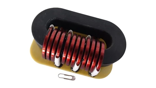
Inductors are fundamental magnetic components widely used in switching power supplies and power conversion systems. Their primary role is to convert electrical energy into magnetic energy, store it, and release it when required. Although inductors share structural similarities with transformers, they generally employ a single winding and operate with a simpler mechanism.
In boost-type DC-DC converters, the inductor's storage–release characteristics form the cornerstone of voltage elevation. This article provides an engineering-oriented analysis of the operating principles behind inductor-based boost converters, focusing on electromagnetic energy conversion, voltage behavior during switching operations, and magnetic saturation constraints.
1. Electromagnetic Energy Conversion in Inductors
An inductor's behavior can be summarized through two essential mechanisms:
• Electrical-to-Magnetic Conversion (Energizing Phase)
When current flows through the winding, a magnetic field forms, storing energy within the core.
• Magnetic-to-Electrical Conversion (De-energizing Phase)
When the current path is abruptly interrupted, the collapsing magnetic field forces the stored energy back into electrical form.
These two mechanisms govern the inductor's operation in all boost topologies. The phenomenon is easily illustrated by examining a simple energized coil, as shown below.

2. Voltage Rise During the De-energizing Interval
Once the current path is opened, the inductor must maintain current continuity. If no discharge path exists, the voltage across the inductor rises sharply-limited only by insulation breakdown. This effect provides inductors with their intrinsic boosting capability and explains the polarity reversal observed during magnetic field collapse.
The following illustration reflects this behavior at the moment power is removed.

3. Basic Boost and Negative-Voltage Generation Circuits
By periodically switching the inductor through energizing and de-energizing intervals, a basic boost conversion structure is formed:
• ON phase: the inductor stores magnetic energy.
• OFF phase: the inductor releases energy through a diode, producing a voltage greater than the input voltage.
Reversing the rectifier direction results in negative-voltage generation. These minimal circuits are at the foundation of modern switching topologies, including Boost, Buck-Boost, SEPIC, and Flyback.
The following diagrams illustrate the minimal positive and negative voltage generator structures.


4. Practical Implementation Using Semiconductor Switches
In practical power electronics, mechanical switches are replaced by semiconductor devices such as MOSFETs and BJTs. This allows for high-frequency switching while preserving the same underlying energy-transfer physics. The simplified diagrams below demonstrate this evolution.

5. Magnetic Saturation: The Operating Limit
The inductor's energy storage capability is constrained by the magnetic core material. Saturation occurs when the core reaches maximum flux density, resulting in the following:
• Rapid decline in inductance
• Sharp increase in current
• Higher copper and core losses
• Potential thermal and switching-device failure
Avoiding saturation requires selecting appropriate core materials, controlling ripple current, and defining suitable operating frequencies.
The behavior of a boost converter is fundamentally dictated by electromagnetic energy conversion within the inductor. Understanding these principles enables engineers to extend the concepts to more complex converter architectures and optimize magnetic component selection for real-world designs.