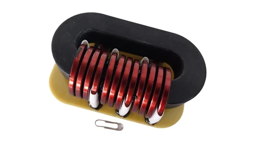
In today's pursuit of extreme power density, power engineers are locked in a "Material War." To squeeze higher efficiency out of shrinking spaces, we are pushing switching frequencies higher and higher, only to hit an immovable wall: Core Loss. Traditional ferrites, while low in loss, are limited by their permeability and saturation points. On the other hand, single-material metal powder cores often fall short in high-frequency interleaved topologies due to magnetic leakage and coupling interference.
When your power module runs scorching hot at full load, or when you're forced to increase inductor volume just to maintain efficiency, the core of the problem may not be the circuit topology-it's the logic of the magnetic material pairing. Today, we will deconstruct a key Magsonder patent (US 11,430,597 B2) to see how the crossover of Metal Powder Cores and Amorphous Laminations solves the efficiency bottleneck.
The Innovation
In this patent, Magsonder proposes a disruptive Hybrid Material Architecture. The core of this innovation isn't about finding a "magic bullet" material, but rather placing materials with different physical properties exactly where they belong.
Division of Labor: The patent deconstructs the magnetic core into three parts: the middle columns, the yokes, and the side columns.
High Magnetically-Permeable Side Columns: This is the soul of the technology. We introduced Amorphous Material or high-permeability Ferrite as the side columns.
Magnetic Path Optimization: By ensuring the Magnetic Permeability of the side columns is significantly higher than that of the middle columns, we force the magnetic flux lines to shift their trajectory, guiding what would be stray leakage fields into high-efficiency, low-reluctance paths.
The resulting "chemical reaction" allows the metal powder core to handle large currents with its anti-saturation capability, while the amorphous material minimizes cycle loss through its extremely low coercivity.

How It Works
To understand the mechanics of this technology, we need to observe the behavior of magnetic flux lines under complex loads.
1. Physical Architecture Breakdown
Middle Column Core (1): Located at the center, carrying the windings. It uses metal powder cores (e.g., Fe-Si-Al) to handle main power currents via high saturation flux density.
Upper and Lower Yokes (2, 3): Acting as connectors to close the magnetic circuit.
High Magnetically-Permeable Side Columns (4): Set parallel on the outer sides. The patent requires their Magnetic Permeability to be no lower than 200. If amorphous laminations are used, this value can even exceed 5000.
2. Automatic Selection of the Reluctance Path
In interleaved parallel circuits, mutual inductance between phases is a primary source of loss. According to the "Principle of Minimum Reluctance," when side columns possess extremely high permeability, the interference flux generated by the two-phase inductors will preferentially close through the side columns (4) rather than entering adjacent winding areas.
Coupling Suppression: The side columns act as a "magnetic highway." Because the permeability $\mu$ is extremely high and the reluctance is low, the Coupling Coefficient between phases is drastically weakened.
Loss Reduction: The laminated structure of the amorphous material effectively blocks Eddy Current Loss. Combined with the soft saturation of the metal powder core, the overall core maintains extremely low heat generation even in high-frequency environments above 100kHz.
3. Precision Air Gap Positioning
The patent adjusts the inductance value by setting controlled Air Gaps between the middle columns and the yokes. Because of the low-reluctance path provided by the side columns, magnetic leakage is effectively contained, reducing induced current losses in external metal enclosures.

Use Cases
This hybrid material technology is already widely implemented in Magsonder's high-performance magnetic components:
Scenario 1: Data Center Server Power Supplies (CRPS)
In the quest for 80 PLUS Titanium efficiency, PFC inductor loss is critical. By using amorphous laminations in the side columns, Magsonder reduces high-frequency core loss by approximately 15%-20%. This not only boosts conversion efficiency but also mitigates the risk of shortened electrolytic capacitor life caused by inductor heat.
Scenario 2: Automotive DC-DC Converters
Electric vehicles demand near-obsessive space and weight savings. Inductors designed with this patent utilize the low-reluctance path of the side columns to significantly reduce yoke thickness. While maintaining the same inductance, the Power Density is increased by nearly 30%, effectively lightening the front-chassis load.
Scenario 3: High-Power Ultra-Fast Charging Piles
In high-current interleaved PFC topologies, inter-phase coupling makes current control exceptionally complex. Magsonder's side column solution reduces the coupling coefficient to negligible levels, simplifying control algorithms and enhancing system Stability during extreme load switching.
Future Outlook
With the proliferation of third-generation semiconductors (GaN/SiC), switching frequencies are marching toward the MHz range. Traditional single-material cores have hit a physical ceiling.
This Magsonder patent reveals a vital trend: the future of magnetic components does not belong to a single material, but to the era of Multi-Material Synergetic Design. By compositing nanocrystalline, amorphous laminations, and advanced metal powders, we can find a new equilibrium between frequency, efficiency, and volume. This is not just a victory for magnetic theory; it is the perfect fusion of manufacturing process and material engineering.
Magsonder's "High Permeability Side Column" patent technology provides the perfect efficiency solution for high-frequency, high-current applications through material complementarity.