In On-Board Chargers (OBC), the PFC inductor is critical for ensuring charging stability. Taking a 6.6kW OBC as an example, the internal topology typically includes 2-phase interleaved PFC inductors, 2 LLC main transformers, 2 resonant inductors, 2 common-mode inductors, and output rectification/filtering inductors. Today, we will explore the design flow through a practical PFC inductor design case.
01. Design Input: Defining Performance KPIs
Before designing the PFC inductor, the operational objectives must be defined. For a standard 6.6kW OBC, the requirements are:
Input Voltage Range: $176V-276V$ (Adapting to various grid inputs).
Output Power: $6600W$ (The core task for energy conversion).
Output Voltage: $400V$ (Providing a stable high-voltage DC bus for downstream circuits).
Efficiency: $\approx 95\%$ (High-efficiency conversion to reduce thermal loss).
Switching Frequency ($f$): $40kHz$ (Determining the operational cadence).
Ripple Current: Set at $30\%$ of the maximum peak current (to ensure current stability).
Operating Flux Density ($B_m$): $0.5T$ (To ensure magnetic performance stability).

02. Five-Step Design Methodology
Step 1: Calculate Maximum Duty Cycle ($D_{max}$)
In a Boost PFC circuit, the relationship between input and output voltage is $\frac{U_o}{U_{in}} = \frac{1}{1-D}$, rearranged as $D = \frac{U_o - U_{in}}{U_o}$.
Using the minimum input $176V$ (peak value after rectification) and $400V$ output:
$$D_{max} \approx 0.378$$
This defines the upper limit of the power switch's conduction time.
Step 2: Calculate Peak Input Current ($I_{pk}$)
Based on power conservation ($P_{in} = \frac{P_{out}}{\eta}$):
$$I_{pk} = \sqrt{2} \times \frac{P_{out}}{\eta \cdot U_{in(min)}}$$
Substituting $6600W$, $95\%$ efficiency, and $176V$ input:
$$I_{pk} \approx 55.8A$$
This peak value guides the selection of magnetic components to prevent saturation.
Step 3: Calculate Inductor Ripple Current ($\Delta I$)
Per design requirements ($30\%$ of peak current):
$$\Delta I = 0.3 \times 55.8 \approx 16.7A$$
Controlling ripple reduces current fluctuations and prevents "unstable charging" states.
Step 4: Calculate Inductance ($L$)
Inductance determines energy storage capacity:
$$L = \frac{\sqrt{2} U_{in(min)} \cdot D_{max}}{\Delta I \cdot f}$$
Substituting the data yields $L \approx 141\mu H$. This ensures a sufficient "energy reservoir" for stable conversion.
Step 5: Calculate RMS Current ($I_{rms}$)
RMS current is used to evaluate thermal dissipation. Based on $I_{rms} = \frac{I_{pk}}{\sqrt{2}}$:
$$I_{rms} \approx 39.4A$$
This value is used to design the cooling solution to prevent thermal shutdown.

03. Software Simulation & Verification
Post-theoretical calculation, professional design software (using "Sendust II" 184 magnetic core, OD $1.4 \times 2$ as an example) verified the parameters:
Core Specs: Sendust II, OD $46.74mm$, ID $24.13mm$, Path Length $10.74cm$, Cross-sectional Area $1.99cm^2$.
Winding Specs: Wire diameter $2.14mm$, wire length per turn $6.21cm$.
Loss Analysis: DC Loss $2.23W$, AC Loss $9.96W$, Total Loss $13.53W$.
Thermal Profile: DC temp rise $81.0^\circ C$, AC temp rise $118.0^\circ C$.
04. Process Evolution: Driving Performance Breakthroughs
The PFC inductor has undergone several generations of innovation:
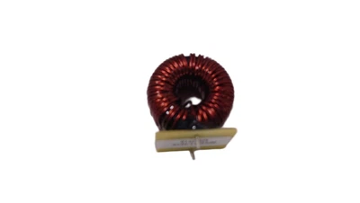
Gen 1: Multi-strand Circular Wire (Parallel Winding). Common in early designs but limited by high-frequency losses and poor window utilization.
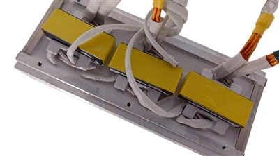
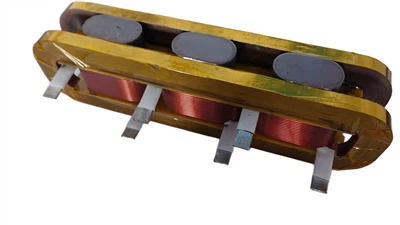
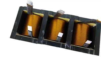
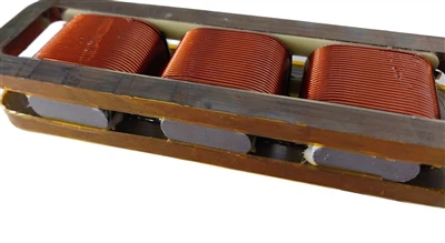
Gen 2: Flat Wire Vertical Winding. Increases effective conductor surface area, reduces skin effect losses, and optimizes magnetic core space utilization, significantly improving power density.
05. Conclusion
The final evolution into an Interleaved PFC design paired with Ferrite cores and Flat Wire Vertical Winding balances current distribution, reduces ripple, and meets the rigorous requirements for OBC miniaturization and high reliability.